Seal Head Introduction
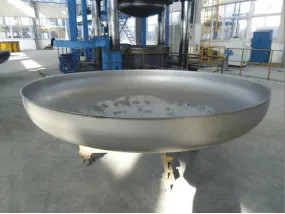
Head stretching hydraulic press is suitable for cold pressing, bending and stretching forming of metal sheets. It is a special equipment for producing large heads, drawing cylinders and large metal containers. The head forming part is shown in Figure 1.
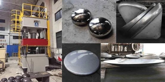
There are many kinds of heads, which can be divided into pressure-bearing heads and atmospheric pressure heads according to their uses; according to their shapes, they can be divided into elliptical heads, butterfly heads, spherical crown heads, hemispherical heads, bow heads, Flat-bottomed head, conical head, etc.
As an indispensable part of atmospheric pressure and pressure vessels, the head is widely used in pharmaceutical, food, chemical, biological, water treatment, environmental protection, electric power, boiler pressure vessels and other fields.
The head production line realizes the full automation of the feeding, centering, oiling, pressing, and discharging of the head pressing process, which maximizes the processing efficiency and quality of the head and reduces the labor intensity of workers.
The Overall Structure Of The Production Line
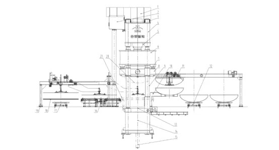
The outline drawing of the head stretching hydraulic press and production line is shown in Figure 2. The body of the head stretching hydraulic press adopts a four-column or preloaded split frame structure. Generally, the head drawing hydraulic press of the formed parts adopts a four-column type, which has a simple structure, is economical and practical, and is guided by the four-column. The head part with high precision requirements adopts a prestressed frame structure and is guided by four-corner and eight-sided plane guide rails, with high guiding precision and strong anti-eccentric load capacity.
Head Stretching Process
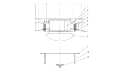
1-stretching slider 2-blank cylinder 3-upper die quick change device and barrel 4-die ring 5-blank slider 6-blank ring mounting flange 7-blank ring 8-punch 9- Workpiece 10 – Die 11 – Ejector Rotary Device
The drawing process of the head drawing hydraulic press is shown in Figure 3. The punch is fixed on the upper die quick-change device on the drawing slider and on the barrel, and the die ring is installed in the blanking slider. Different specifications are used for different workpieces. Standard die ring, the blank holder is fixed on the die ring, the female die is fixed on the mobile worktable, and the ejector rotating device is fixed in the lower beam.
Head Stretching Hydraulic Press Stretching Flow Chart
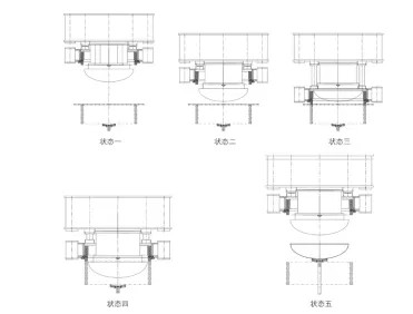
Figure 4 shows the flow chart of the stretching movement of the head stretching hydraulic press. State 1 is the initial position of the hydraulic press. State 2 is that the stretching slider and the blank holder are rapidly approaching the workpiece together under the drive of the stretching cylinder. State 3 is The stretching slider does not move, and the blank holder goes down and the blank holder presses the workpiece. The state 4 is that the blank holder does not move (with blank holder force). The stretching slider moves down to stretch the workpiece, and the state 5 is the stretching slider. , The blank holder slides back in place, and the lifting rotary device lifts up the workpiece. The process flow is as follows: initial position of the hydraulic press → rapid lowering of the stretching slider and the blank blanking slider → rapid lowering of the blank blanking slider → pressure of the blank blanking slider → downward tensioning of the stretching slider to stretch the workpiece → holding pressure delay and Decompression→stretch the slider and press the edge slider return→lift up the rotating device to lift the workpiece→(after the workpiece is removed) jack up the rotating device to return. The ejection start time of the jack-up rotary device can be activated by the position set in the return stroke of the slider, so as to increase the working frequency.
Control System
The hydraulic system design of this line needs to achieve independent control of the pressure of the stretching slider and the side blanking slider, so as to ensure that the pressure of the stretching slider and the blank blanking slider can be controlled in real time without interfering with each other during the production process. Independent hydraulic control circuits are set up for the stretching, edge pressing and ejection of the machine, and pressure proportional control valves and pressure sensors are set in each circuit. Digital display and pressure proportional control to realize the process of blank pressing, stretching and ejection of head forming parts.
At present, the company has developed a series of head production lines. The opening height of the main machine, the stroke of the slider, the work surface, and the tensile blank holder force can be determined according to the needs of users and the needs of the pressing process. The head production line independently developed by the company realizes the full automation of feeding, centering, oiling, pressing, and discharging in the head pressing process, which maximizes the processing efficiency and quality of the head and reduces the labor intensity of workers. Its numerical control operating system only needs to input the relevant parameters of the head to realize the operation of the equipment during operation, which greatly simplifies the operation of the equipment.
